- Author Calvin /
- 0 comments /
- December 8, 2025
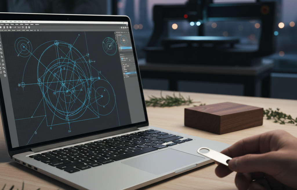
Welcome back! In our first article, How to Use AI to Find Your Next CNC Milled Product, we used AI, a little common sense, and a little research to select the Leaf-Lock Herb Stripper as our next product. Now, we need to translate that idea into machine instructions using VCarve Pro. If you plan on using the CNC at the Kzoo Makers location, get in touch with Ryan about getting access to the makerspace license for installation at home. You will need to build your final file on location, but we currently only have two computers set up with this software, so the best practice is to do as much as you can before coming in to make sure everyone has access when they need the systems. That brings me to a very important part of the equation. Make sure you have a USB thumb drive you can use during this process. The simplest and most effective way to get your file from your brain to the end of the CNC mill carving out your design is to store everything related to the project on a thumb drive. It saves time vs emailing files, downloading them to the CNC computer, and then forgetting to delete them, leaving a digital mess that adds up over time. It also keeps your designs safe so you can be sure you are the only one making your exact product. This installment will walk you through the entire design process, ensuring your toolpaths are safe, efficient, and ready for the CNC.
Setting Up the Digital Workspace
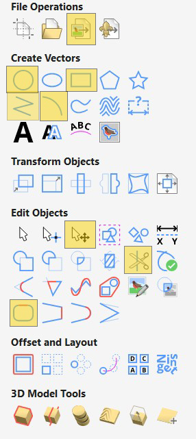
Defining your material’s size and the job’s origin is the single most important step for a safe and accurate cut. Since we are using scrap wood, precision is key. However, we want our design to be flexible enough to add to any other project easily. Instead of trying to find a piece of material and using that as a design restraint, we are going to just make our material size much larger than we need it to be for now. We can always adjust it later, and we will. In the images below, I have highlighted all of the tools we will be using in this article for reference.
Define the Arbitrary Job Size (Design Flexibility)
We are starting with the Herb Stripper design itself, assuming it will be cut from a thicker piece of scrap wood (e.g., ¾”+). We will go over why we want such thick material in the final article, Post Carve Processing. We will define the job area as a generic, large sheet.
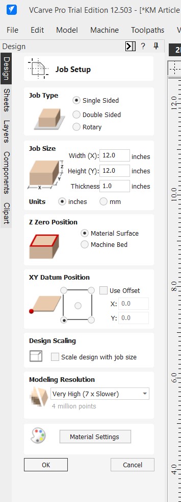
- Open VCarve Pro and click “Create a new file”.
- Job Type (Single Sided):
- Width (X) and Height (Y): Set these to a generous, arbitrary size like 12.0 inches x 12.0 inches.
- Thickness (Z): Input the intended thickness of the stock you are cutting from (e.g., 1”).
- Z Zero Position: Select “Material Surface”.
- XY Datum Position: Select the bottom-left corner.
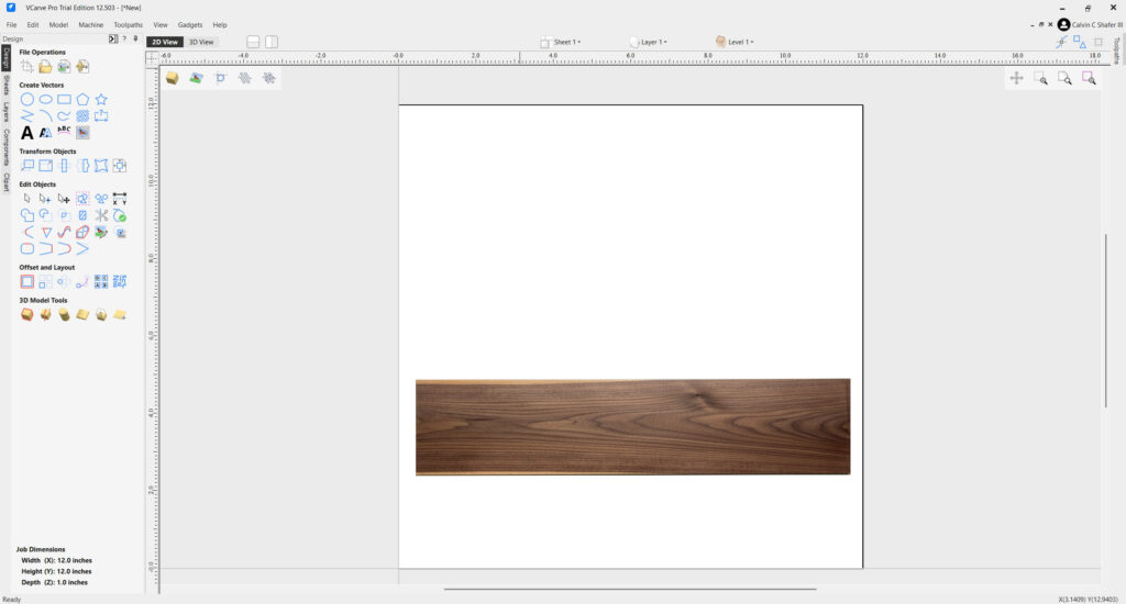
The white space you see here represents the stock material you are cutting your design from, as seen from above. If you are standing at our CNC, that point would be the corner closest to the computer. Since we are talking about orientation, now is the best time to consider your wood grain and bit sizing. For most projects cut from solid hardwood boards, you will be orienting the board lengthwise away from yourself on the CNC table. So when you design, you will be placing your stock in the horizontal direction as indicated in the image below.
If you haven’t had a lot of experience using a router, here’s why that matters. Any spinning tool has a chance when cutting through solid wood to grab the grain and rip out a sliver of material instead of making a clean cut as the bit travels across the grain of the board. What that means for design, Is we need to try to place our final design on our material so it avoids hard angled corner cuts in the direction of the bit. Our machine turns clockwise as viewed from above. That means if we were to cut the border of the above board, the top left and bottom right corners have a risk of tear-out. There are ways to mitigate this problem, I reccomend searching YouTube for tutorials. Most of the time your cuts will be just fine as long as you don’t try to push the settings (pass depth, cut travel speed, spindle speed, bit type, etc.) too hard.
Creating the Vectors (The Design)
We will use simple drawing tools to create the Herb Stripper’s functional design. I will be using my personal research from the first article for the sizes and details for this design. You should play around with the idea and make your design unique and interesting, but if you want to follow along line by line with me and make one for yourself, feel free!
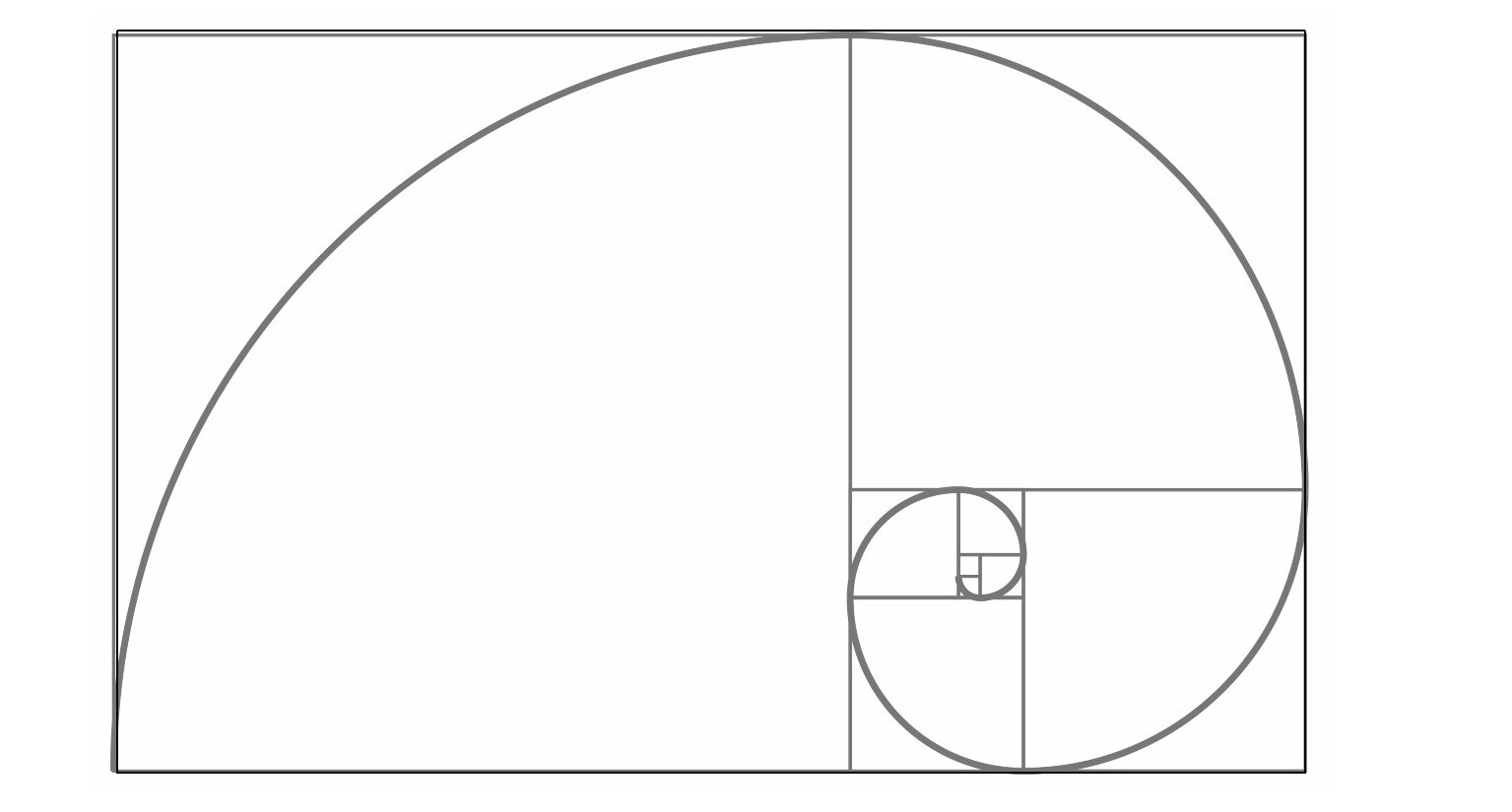
It helps to have some design sense or understand how certain shapes make us feel more connected to an item… or just use the golden ratio. For this design, we will be doing just that. Right click the image below and save it to your system.
- Draw the Outer Shape:
- – In the menu on the left under File Operations, click on the third icon to import the image you just saved of the golden ratio.
- – Using the Rectangle Tool, Create a rectangle in the white space that is 4” by 2.5”. With tools in Vcarve, you have two options. You can set the parameters then click on the workspace to get a defined size, or click and drag the cursor.
- – Now we will move the golden ratio image to align with the rectangle we just created. We can use the Transform Mode, third icon in Edit Objects, to resize the image to match as closely to our rectangle as we can get.
- – Use the “Draw Arc” tool to create a clean arc in each section of the golden ratio until you have the largest 3 arcs drawn.
- – Use the Draw Line Tool to connect the open end of the arc on the left to the open end of the smallest arc on the right.
The final shape must contain all 7 holes while leaving at least 0.25 inches of solid wood around the outside of the largest holes for structural integrity. Now that we have the basic shape for our design, we can select and delete the golden ratio image and the original rectangle, leaving behind the outline of our tool. Any components you make in Vcarve will be composed of nodes, or points of interest related to that shape. An important factor to creating designs that work with the CNC system is making sure all of your nodes are connected. Just like the nodes in a normal selection tool that let you drag and resize or reshape something, the nodes in Vcarve allow you to change the behavior and shape of the lines that make up a part. Press ‘N’ on your keyboard to go to Node Edit Mode. You should notice all of your selected red dashed lines turned black, with an arrow on each line, and several types of squares along their path. For us to be able to cut anything out, the segments all need to be connected in a closed loop. The slightest disconnect between our points will cause a failure when we try to generate toolpaths later, as the system doesn’t have clear parameters to engage with.
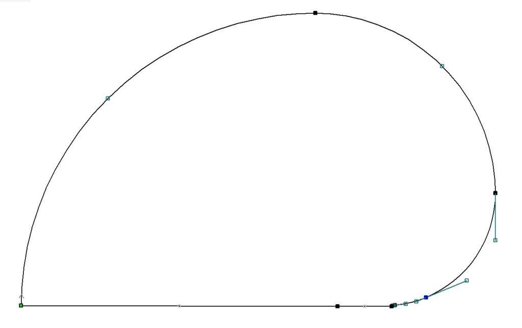
The good news is, Vcarve has a tool just for this purpose. Under the Edit Objects header, you will find a blue rectangle with a red section. This is the Join tool. With your outline selected, open the Join tool. You should see the numbers of closed and open vectors in your selection. We currently have 4 segments making our outline, and by clicking the Join button, Vcarve will recognize any points that are within the tolerance zone of one another and connect them for us.
Now that we have a solid outline, which is closed, we can take a closer look at the Nodes. The green Node represents where the tool will start when it cuts this path. The arrow shows the direction the tool will travel. Empty green Nodes will edit a feature of a segment, and solid black Nodes will edit the joined endpoints of the segments. If you click Join and you are left with an open shape still, zoom in on the black nodes using the mouse wheel and make sure nothing goofy is going on where the endpoints are near one another. There should also be a small Arrow near the solid green node. This indicates the direction the cut will travel. It is always a good idea to check this when you do layout to make sure you avoid tearout scenarios. If you need to change the direction of the cut, or the starting point, right click on the green node and make your changes. I highly reccomend for this project that we set the solid green starting point inside the largest hole. As the machine pauses and lowers, the bit will spin in place for a moment, and this can often leave behind a small indentation at this point along the entire piece. By setting your start point in an area that is already cut out, we can avoid extra work during the cleanup process. But first, we need to know where the holes will be.
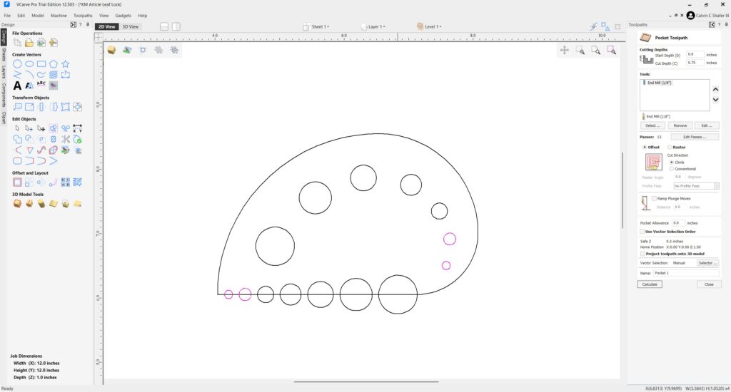
- Draw the Holes:
- – Use the Draw Circle tool to create 2 holes of each size: .126” (3.18 mm), .187” (4.75 mm), .25” (6.35 mm), .325” (8.26 mm), .4” (10.16 mm), .5” (12.7 mm), .6” (15.24 mm).
- – Align one set of holes along the straight line, leaving enough space between each hole to make sure your wood doesn’t get too weak.
- – Align the second set of holes along the curved line of the tool. This creates different options for the end user. They can pass herbs through the holes, or press the flat side of the tool against a cutting board over the stalks and pull through that way.
Believe it or not, we’re done designing! We now have a shape and layout for our Leaf Lock, which we can assign Toolpaths to so the software knows what to tell the machine to do later.
Toolpath Strategy
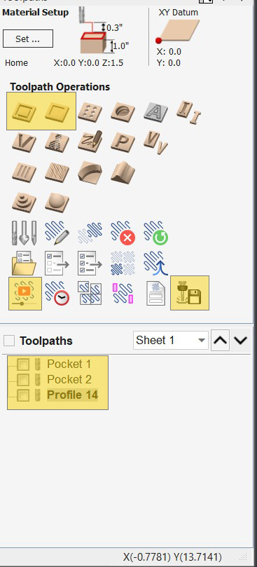
With the design finalized, we create the instructions (Toolpaths) that the CNC machine reads. Since we designed the tool to be 1″ thick, we will need to use multiple passes to remove the wood based on the cutting bit we are using. As a general rule, each pass should be no deeper than the tool is wide. For this project, we will need 2 tools: a ¼” Downcut End Mill, and a ⅛” Downcut End Mill. The narrower your bit, the easier it is to break, so with ⅛” bits, you might want to buy a few at a time. You open the Toolpath menu by clicking the labeled tab in the top right corner of Vcarve. Next, you will want to click on the pin icon in the top right corner of this menu. If you don’t, the menu will just keep collapsing automatically, making you pull your hair out and say things your mother would not care to hear you say.
Toolpath 1: Drilling the Holes (Pocket Toolpath)
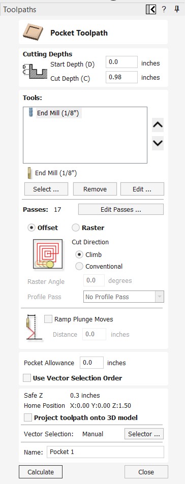
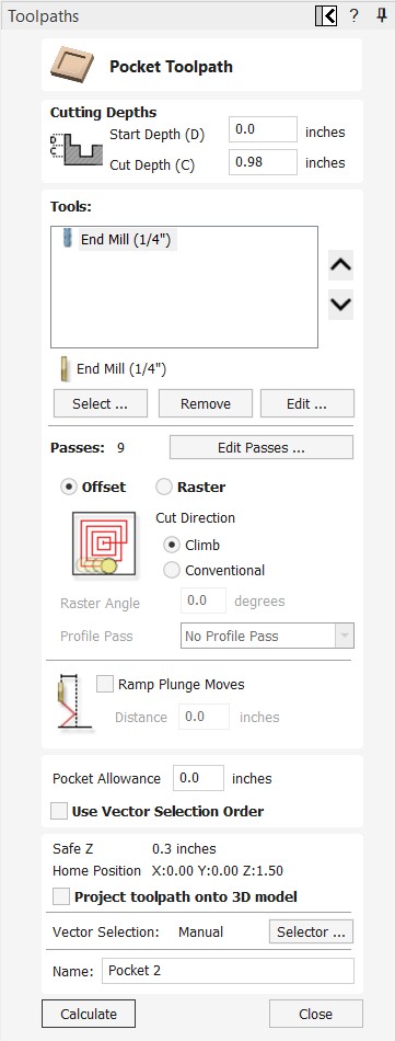
We use a Pocket toolpath instead of a Profile or Drill path to ensure the bit accurately carves the centers of the holes safely. A pocket path will use the end mill to remove any material inside the selected shape. A Profile path will leave the center material, and with small spaces like this, that chunk of wood can bang around and ruin your evening if it decides to get in a fight with your bit. As a general rule, I try not to leave any interior shape that is smaller than an inch in diameter. So with all of our cuts much smaller than that, even though it takes a bit longer, its better to just pocket clear our holes.
- 1. Select the two smallest sizes of your circle vectors.
- 2. Click the “Toolpaths” tab and choose “Pocket Toolpath”.
- 3. Cutting Depth: Set the Cut Depth to .01” deeper than your material thickness to make sure you get a clean cut on the bottom side of your material.
- 4. Tool Selection: Select the 1/8″ (0.125″) End Mill. This bit is small enough to machine the smallest holes accurately. Fortunately, the tool settings in Vcarve are generally safe to use for your project. As you create and run programs on the machine, you will become more familiar with how to use feeds and speeds to make faster and cleaner cuts across various materials.
- 5. Click Calculate: Preview the toolpath by clicking Preview All Toolpaths in the window that opens next. The machine will use this Toolpath we just created to carve each hole to its specified diameter. To get back to your design, click the 2D View near the top left corner of the design window.
- 6. Select all of the larger holes and repeat steps 1-5. This time, select the ¼” (0.25”) End Mill.
We are using the smaller, slower, more fragile bit only for the spaces the ¼” bit can’t physically get inside. Your tooling is the most common expense for CNC milling operations. Your best bet is always to use the thickest bit you can to do the work without making too much waste. For most processes a ¼” bit with a ¼” shank will be just fine.
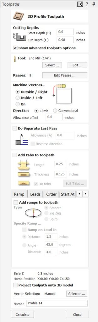
Toolpath 2: The Cutout (Profile Toolpath)
This is the final cut that defines the perimeter of our product.
- 1. Select the outer vector only.
- 2. Choose “Profile Toolpath”.
- 3. Cut Depth: Set this to 0.98″ (just shy of full depth).
- 4. Tool Selection: 1/4″ End Mill for a faster cutout
- 5. Machine Vectors: Select “Outside / Right”. This compensation setting is essential, it tells the cutter to run its center outside your drawn line, preserving the exact dimension of your shape. If we were using a Profile Toolpath to cut out an interior hole feature, you would select Inside/Left instead.
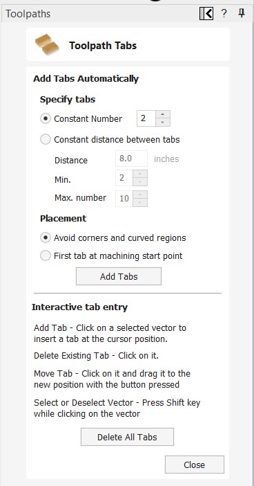
Alternate Method: Adding Tabs
Tabs are non-negotiable for safe CNC operation if you want to cut all the way through your board and still have a piece that is easily removable. They are small connectors that prevent the finished part from becoming a destructive projectile during the final pass. In our example we cut through .98” in a 1” board, leaving behind what is called an ‘onion skin’ or thin layer that doesn’t get cut by the CNC at all. This means a little more work after the CNC run, but it is also more secure than tabs. But, in case you would rather use tabs than an onion skin, here’s how:
- 1. Check the box “Add tabs to toolpath”.
- 2. Click “Edit Tabs”.
- 3. Set the dimensions: I recommend 0.25″ Length and 0.125″ Thickness at a minimum for most projects. Larger tabs will hold stronger, but are also more difficult to break away cleanly later or require more time cleaning them up in the finishing stage.
- 4. Manually place 3-4 tabs strategically on the perimeter, avoiding sharp corners where they may break out prematurely. You can just set a Constant Number and click the Add Tabs button, but I have found common sense placement beats automated nearly every time.
- 5. Calculate the toolpath.
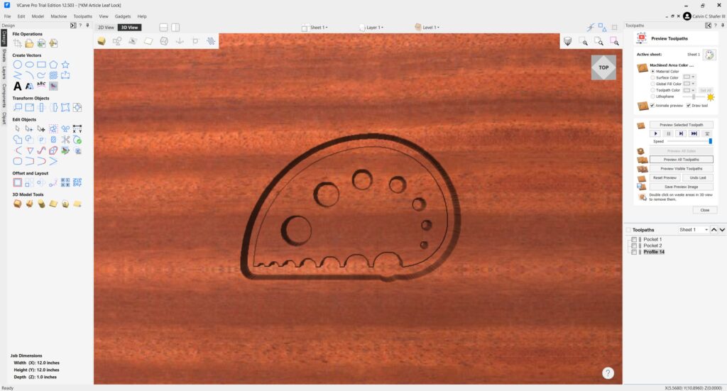
Simulating The Cut
Once you have all of your toolpaths generated, its a good idea to open the Toolpaths tab and click on the Preview Toolpaths button in the bottom left corner of the Toolpath Operations. Make sure all of your toolpaths listed on the bottom of the Toolpaths tab have a checkmark in their box. Click Reset Preview and then Preview All Toolpaths to watch Vcarve simulate the tool paths, resulting in what you should expect to see when you run the CNC. This is a good time to check the order of your toolpaths. You want to order them such that the weakest bits cut first, making sure your material is as rigid as possible. Next, you cut all interior features. Finally, you cut the outline, separating your part from the stock material. Watch the simulation a few times, slow it down if needed using the Speed slider, and make sure the process is going to cut things in an order that makes sense for your project and bits.
Saving and Exporting the File
The final steps translate your VCarve work into machine-readable code.
- 1. Save the Project File (.CRV): Go to File > Save As and save your VCarve Project file. This is the editable file for making future tweaks.
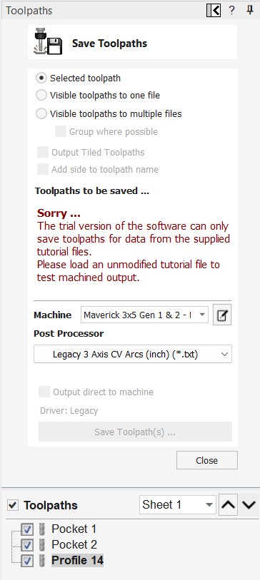
- 2. Save the Toolpaths (G-code) (This step can only be done on location with the makerspace license):
- – In the Toolpaths tab, click “Save Toolpaths”.
- – Select Toolpaths to Save (select all toolpaths).
- – Crucially, select the correct Post Processor for your specific machine (e.g., Maverick 3×5 Gen 1 & 2 – Mach 3, Post processor, Legacy 3 Axis CV Arcs (inch)(*.txt)). Choosing the wrong post-processor can cause major errors.
- – Save the .txt file to a USB drive for transfer to the CNC station.
- – Don’t worry about that error message below. It will not be there while you are saving your file at the space on the dedicated computers.
Next Steps:
Your design is finalized and ready for cutting! In the next article, Safe Production, we will cover how to size your stock material to make your first units, set up the Legacy Maverick CNC, and create our first small batch of product!